 | MiST TVC |

|
TVC's parameters just briefly:
- 3 graphics modes (Horiz x Vert x Colors): 512x240x2, 256x240x4 and 128x240x16
- 64K RAM és 16K video ram, plus 16K+4K Basic+OS ROM. Memory is paged in 16K banks,
- progrrammable sound generator (using only TTL chips)
- Motorola 6845 CRTC character address generator
- Composite video and analogue RGB (+SYNC) output
- Built-in joystick plus two dedicated Atari style DB9 joy port
- 4 card slots for expansion cards
I divided the machine into logical units, following the FGPA design lines. Of course I needed the documentation and the schematics to learn this system. I spent a couple of days to study them.
So my main logical parts are:
- Clock generator making the different clocks the system needs
- Z80 CPU,
- 6845 CRTC, graphics address generator
- display module (VideoCtrl),
- sound module (SoundCtrl),
- memory, ROM and RAM,
- video memory (inside the VideoCtrl),
- memory management unit (Pager),
- PS/2 keyboard interface.
I used others' work, so the two main parts the Z80 and the CRTC comes form outside. Everything else is my work, based on the documentation and the schematics. The FPGA main clock is 100MHz for the SDRAM, then this one is divided down for the required other frequencies:
- 12.5MHz pixel clock for the mode 512 horizontal pixels, 2 colors,
- 6.25MHz pixel clock for the mode 256 horizontal pixels, 4 colors,
- 3.125MHz pixel clock for the mode 128 horizontal pixels, 16 colors,
- 1.5625MHz the "character" clock for the CTRC.
Knowing that the MiST SDRAM module needs 8 cycles to do one random memory access, the Z80 CPU can go up to 12.5MHz in this design. The original machine used 3.125MHz only by the way.
Video Controller
TVC had 3 different video modes, 3 different horizontal resolution, but form the hardware point of view, there was only one simple shift register that was clocked by the actual pixel clock, and uses a group of bits for the video signal. Loading and shifting the register was the same for all modes, but using the bits of it was different.- In 2 colors mode each bits presents a pixel as expected B7-B6-B5-B4-B3-B2-B1-B0. The bit then selected a color from a palette, providing the RGBI color information
- In 4 colors mode we need 2 bits for a pixel, as 1C0-2C0-3C0-4C0-1C1-2C1-3C1-4C1. This 2bits again pointed to a palette so one of the 4 RGBI colors could be selected.
- In 16 colors mode we need 4 bits for a color, such as 1I-2I-1G-2G-1R-2G-1B-2B. In this mode there is no palette, bits provide the RGBI color directly.
In my solution this logic was easy to implement. The original TVC had memory contention (CPU was halted when the video controller read the video memory). This method is called clock stretching in the documentation. Thanks to the internal memory of the FPGA, I don't need this. Dual-Port ram can be accessed from both sides without contention.
In case of the TVC there is no VGA mode. It would have been to complicated to implement it, so I decided to produce two cores. One core works in the normal RGB+Sync mode, able to drive the Euro Scart connectors, while the other one works in VGA mode, using different clocks for the video controller. The VGA version also skips the CRTC, so it was removed, and a simple sync generator is used instead.
Sound
Sound generator in the TVC is a simple divider (counter) with two parts: 12 bits (4046) programmable divider, and a fixed 4 bits (16) divider. The main clock for the counter is 3.125MHz, same as the CPU clock. The audio level is controlled by an 4 bits R/2R DAC. Needless to say, that this was an easy task in an FPGA. Finally, the generated signal goes to a delta-sigma DAC, which drives the audio output. Since TVC is a mono machine, both channels get the same signal.Memory paging
The documentation tells all the details about the memory paging in the TVC, so based on that it was an easy job. It's actually nothing more than a few logical equations. Since the ROM is also in the MiST's SDRAM it made it just a bit harder, but fortunately the module data_io can handle that part. The ROM is loaded into the SDRAM when the core starts (above the first 64K). Then the pages only needs to use some higher bits to page the ROM into the selected memory bank. MiST has 32MB RAM, so this should not be a problem at all.Keyboard
Using a simple PS/2 interface and a lookup table that converts the PS/2 codes to TVC rows and columns. Actually the MiST uses USB keyboards, but the module user_io provides the keystrokes in PS/2 format. I needed to map some keys to special PC keys, like Page Up, Page Down to map all the TVC keys. For the convenient game play, keys Y and Z can be exchanged (as on the Hungarian keyboards).Loading games
I could get the information about the file format .CAS based on some emulator sources. It turned to be quite simple. There is a small header which must be skipped, then just load the bytes into the RAM. All is done as for the others, using the MiST On Screen Display (OSD) and the Verilog module called data_io. After the bytes loaded into the memory, you need to type in the command run to execute the app or game.Images:
Pictures show the core that works in RGB+Sync mode, using the Euro Scart connector of the TV
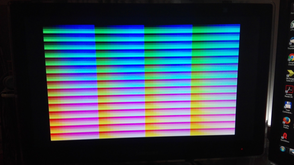
First test of the CRTC
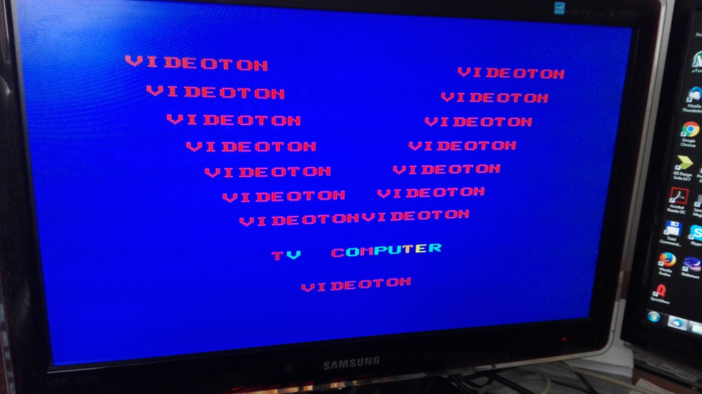
Boot srceen of the TVC with the MiST OSD
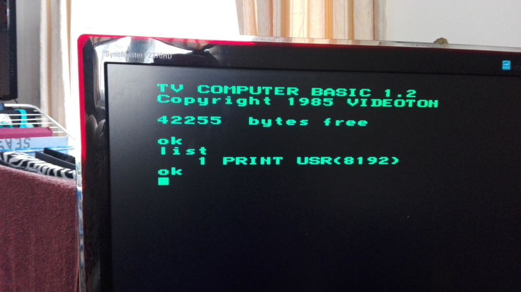
Basic interpreter's initial screen
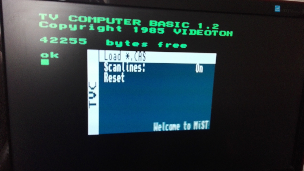
MiST OSD
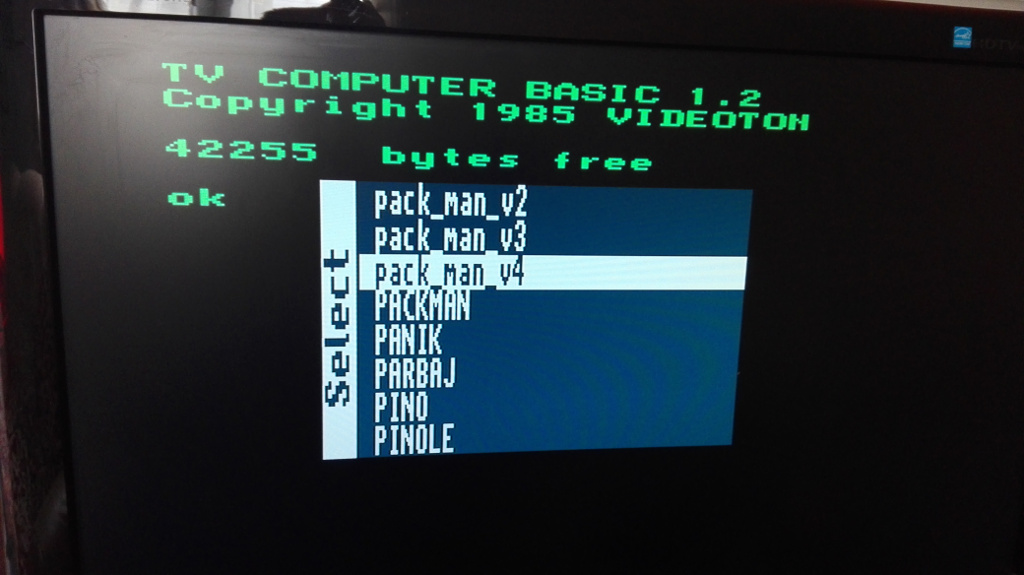
MiST OSD , list of TVC .CAS files
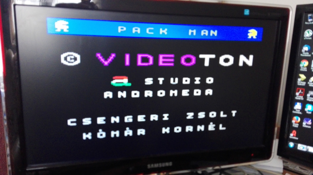
A pack man (pac-man) game, menu
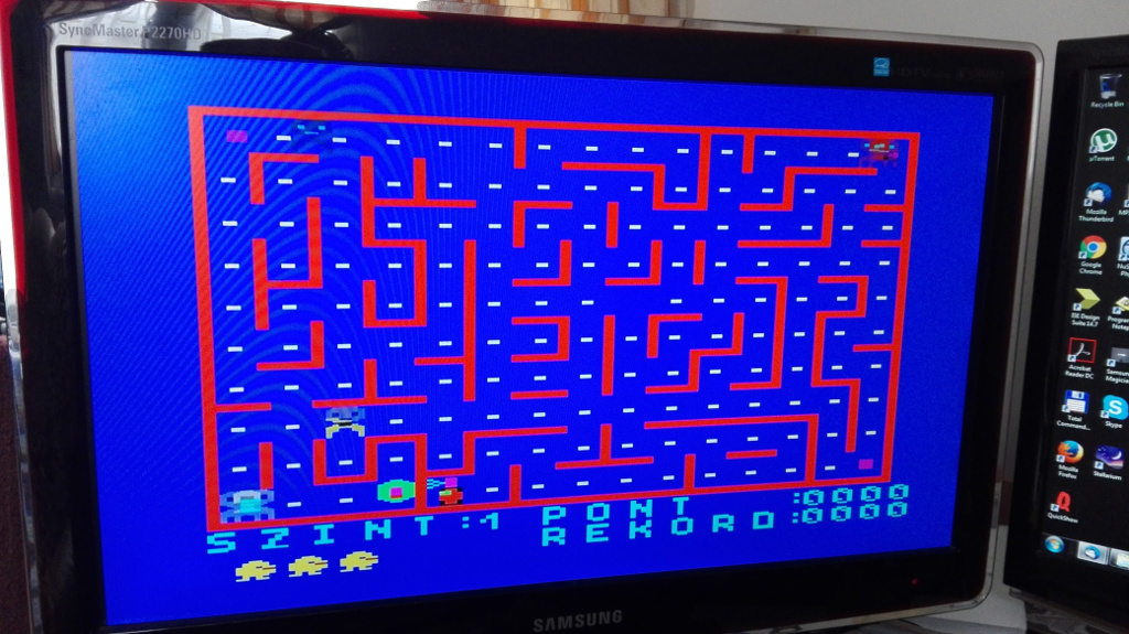
A pack man (pac-man) game, level 1
Downloads:
TVC.RBF - for Euro Scart cable (RGB displays)
TVC.ROM
TVC.RBF - for VGA displays
Some games
Thanks to:
- the original developer of the TVC, what a good machine they have constructed
- to Mike Stirling for the CRTC module. Great work, Mike.
- to the TVC homeserver page, where all the documentations and many more information available
- to Gábor Orvos, who pushed, urged, inspired me to implement this core on the MiST. He was right, it's cool indeed.
Links and references:
[Home | FPGA development]