Colors, Palette manipulation

Colors, Palette manipulation |  |

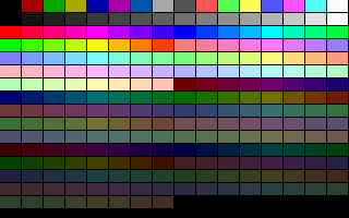
program showpal; uses gfx256; var i,j : integer; begin graph320x200; for i:=0 to 15 do for j:=0 to 15 do bar(j*20,i*12,19,11,j+i*16); readln; text80x25; end. |
The VGA system has a palette for the 256 color modes. This palette stores the color information in the RGB (Red-Green-Blue) format. This means that the palette register contains 3 (1-1-1) components for each base color. You can set the intensity of a base color normally between 00..63 (64 steps), and these define the final color based on the additive color mixing method. Sometimes it's called trichromatic color mixing. Since each component has 6 bits (00..63), the number of the possible colors is 64*64*64 = 262 144. (Note: Modern videocards have 8 bits for each component, but they still have to be compatible with the original VGA standard.)
The videocard has three I/O ports for the palette manipulation:
   Port     Function
   $03C7    Palette component read index
   $03C8    Palette component write index
   $03C9    Palette component data
Register $03C7 and $03C8 points to the palette entry you want to read or write. When you write a new value into these registers, an internal pointer moves to the right place. Then you can use the $03C9 data register for reading or writing the selected palette entry. The data can be set or get by three sequential write or read on the port $03C9. For instance a possible solution in pascal (using the built-in port array):
  { write }
  port[$3c8]:=index;
  port[$3c9]:=red;
  port[$3c9]:=green;
  port[$3c9]:=blue;

  { read }
  port[$3c7]:=index;
  red:=port[$3c9];
  green:=port[$3c9];
  blue:=port[$3c9];
Now the same proceduers in assembly:
procedure SetRGB(reg,R,G,B:byte);                            assembler;
asm
   mov  dx,03c8h       { RGB write register        }
   mov  al,reg
   out  dx,al          { Set the palette index     }
   inc  dx             { $03c9 RGB data register   }
   mov  al,R           { Red component             }
   out  dx,al
   mov  al,G           { Green component           }
   out  dx,al
   mov  al,B           { Blue component            }
   out  dx,al
end;

procedure GetRGB(reg:byte; var RGB);                         assembler;
asm
   cld
   les  di,RGB
   mov  dx,03c7h       { RGB read register       }
   mov  al,reg
   out  dx,al          { Set the palette index   }
   add  dl,2           { $03c9 RGB data register }
   in   al,dx
   stosb               { Red   }
   in   al,dx
   stosb               { Green }
   in   al,dx
   stosb               { Blue  }
end;
|
Note that in the second case we pass the parameter RGB by reference and fill up this one (implicitly this is a byte array) with the color components.
Test
This small program sets the last 192 elements of the palette to the base components, while leaves the first 64 entries as they were set by the BIOS.
|
The result as we see on the screen:
|
Downloads: [ Gfx256 unit | Show Palette | Set Palette ]