Draw a general line

Draw a general line |  |
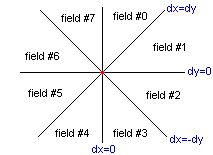
On the following picture the red point in the center shows the start point of a general line. Whatever happens, on a 2D plane there are eight different fields based on the difference of dx and dy, where
  dx := x2 - x1
  dy := y2 - y1

  (x1,y1) is the start point of the line
  (x2,y2) is the end point of the line


|
|
{ line steps for the 8 different directions }
const
   Ntab : array[0..11] of integer=(-321,-320,-319,000,
                                   -001, 000, 001,000,
                                    319, 320, 321,000);
var
   r1,r2,r3,r4,r5 : word; { some space to store temporary data }

procedure Line(x1,y1,x2,y2,color:integer); assembler;
asm
   mov  ES,SegA000     { Screensegment }

   mov  ax,320         { Address calculation }
   mul  y1
   add  ax,x1
   mov  di,ax

   mov  al,Color.byte
   mov  ES:[di],al     { We show the first pixel }

   mov  bx,0101h       { sgn X (BL), sgn Y (BH), both +1 }

   mov  dx,X2
   sub  dx,X1          { DX = X2-X1 }
   jnc  @t1
   neg  dx             { DX = abs X  (where X=X2-X1) }
   mov  bl,255         { BL = sgn X }
@t1:
   mov  si,Y2
   sub  si,Y1          { SI = Y2-Y1 }
   jnc  @t2
   neg  si             { SI = abs Y  (where Y=Y2-Y1) }
   mov  bh,255         { BH = sgn Y }
@t2:
   mov  cx,si          { CX = abs Y }
   mov  r2,bx          { r2 = sgn X sgn Y, we store them }

   cmp  dx,si          { what's the main direction? (X/Y) }
   jnc  @x_ge_y
   mov  r1,dx          { r1 = abs X }
   xor  bl,bl          { sgn X = 0 , X incremental line }
   jmp  @t3

@x_ge_y:
   test dx,dx          { abs X=abs Y=0 (it's only a pixel ) }
   jz   @exit
   mov  r1,si          { r1 = abs Y }
   mov  cx,dx          { cx = abs X }
   xor  bh,bh          { sgn Y = 0 , Y incremental line }
@t3:
   mov  r3,cx          { CX: number of pixels to draw }

   mov  ax,cx
   shr  ax,1           { AX = INT(CX/2) }

   { this main loop draws the line }

@line_loop:
   add  ax,r1          { increment }
   jc   @diag          { diagonal step }
   cmp  ax,r3
   jc   @vhl           { vertical or horizontal step }

@diag:                 { diagonal step }
   sub  ax,r3
   mov  r4,ax          { save AX  }
   mov  ax,r2          { orignal sgn X, sgn Y }
   jmp  @nextplot      { go to draw }

@vhl:                  { vertical or horizontal step }
   mov  r4,ax          { save AX  }
   mov  ax,bx          { computed sgn X and sgn Y  }

@nextplot:             { draw the pixel }
   mov  r5,bx          { save BX  }

   inc  al
   shl  al,1           { AL = (sgn X+1)*2, can be 0,2 or 4  }
   inc  ah
   shl  ah,3           { AH = (sgn Y+1)*8, can be 0,8 or 16 }
   add  al,ah
   xor  ah,ah
   lea  bx,Ntab        { BX points to the right element of Ntab }
   add  bx,ax
   add  di,[bx]        { so we make one step to the given direction }
   mov  al,Color.byte
   mov  ES:[di],al     { put the pixel }

   mov  ax,r4          { saved values back }
   mov  bx,r5
   loop @line_loop     { do the next step }
@exit:
end;
|
Do you understand? Well, I do not. :-) Yes, it's true, once I implemented, it was so clear for me, but right now it's just a mess. So don't be disappointed if you don't get it. Just use it.
Test the result
|
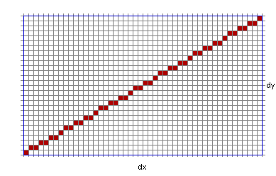
This is what we see on the screen:
|
Downloads: [ Gfx256 unit | Lines ]