Draw pixels and horizontal/vertical lines

Draw pixels and horizontal/vertical lines |  |
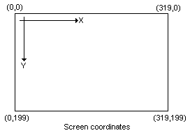
When we are talking about drawing, we think of coordinates of a graphic object. That's fine, but as we know from the lesson 1, the screen is just a simple linear memory area, which contains 320x200=64000 bytes. We assume, that the point(0,0) is the leftmost/upper pixel on the screen. This is general for computers, though it's not the way we use coordinates in Math.

ADDRESS := 320*Y + X ;The same in assembly:
   mov  ax,320
   mul  y
   add  ax,x     { now ax has the address }
We don't have to deal with the segment part of the address, because the entire screen area fits into one
segment (it's smaller than 64K). Remember for this calculation! It's important and we're gonna use it many times.
Setting a pixel
So, let's write our first Pixel procedure:
procedure Pixel(X,Y:integer; Color:byte); begin mem[$a000:320*Y+X]:=Color; end; |
Cool. It would work, though it does not check the parameter values, so giving a wrong parameter can ruin the result. Anyway, why don't we turn this small routine into assembly? We do...
procedure Pixel(x,y,color:integer); assembler;
asm
   mov  ES,SegA000      { Predefined segment base variable }
   mov  ax,320
   mul  y               { 1st step: ax = 320*y     }
   add  ax,x            { 2nd step: ax = 320*y + x }
   mov  bx,ax           { move the address into bx }
   mov  al,color.byte   { that's the color code    }
   mov  ES:[bx],al      { show the pixel           }
end;
|
Here comes the description. In the first line we load the predefined SegA000 into the ES (Extra Segment register). The SegA000 is defined by the unit system, and surely it points to the screen segment. Then we do the calculation by simple MUL and ADD instructions. Once we have the ADDRESS, it moves to the BX, then we load the color parameter into the AL, and in the last line we put the pixel out to the screen. I don't think the assembly version is complicated. Perhaps the only one thing you need to memorize is the way how we pass the color parameter as integer and then later on we get only the lower byte of it. (mov al,color.byte). The Pascal passes bytes as words anyway, so in the Pascal version the Color is a 16bits word as well, even if we can't see this.
Drawing horizontal lines
A horizontal line has four parameters: X,Y,Width and Color. X,Y is the coordinate for the beginning of the line, while Width is the length of the line in pixels. Because on the screen the difference between two pixels horizontally is one byte, the horizontal line can be drawn by a simple loop, like this:
procedure HorizLine(X,Y,Width:integer; Color:byte); var i : integer; begin for i:=0 to Width-1 do mem[$a000:320*Y+X+i]:=Color; end; |
Go to assembly again. The address calculation will be the same as we did it for the procedure Pixel. Then we could have a loop that draws the line. But, because the address difference is one byte, we can use the STOSB (memory fill) instruction in this case.
procedure HorizLine(x,y,width,color:integer); assembler;
asm
   mov  ES,SegA000         { Screen segment      }
   mov  ax,320
   mul  y                  { Address calcualtion }
   add  ax,x
   mov  di,ax              { we need the di register this time }
   mov  al,color.byte
   mov  cx,width           { length of the line          }
   cld                     { stosb will increment the di }
   rep  stosb              { draw the line               }
end;
|
Drawing vertical lines
Technically vertical line is kinda same as the horizontal one. Of course we need a loop that vertically puts the pixels now. Our parameters: X,Y,Height and Color.
procedure VertLine(X,Y,Height:integer; Color:byte); var i : integer; begin for i:=0 to Height-1 do mem[$a000:320*(Y+i)+X]:=Color; end; |
Compare this one to the pascal version of HorizLine above. You wil see that in this case we increment the Y instead of the X. In assembly:
procedure VertLine(x,y,height,color:integer); assembler;
asm
   mov  ES,SegA000       { Screen segment }
   mov  ax,320
   mul  y
   add  ax,x             { Address calculation }
   mov  di,ax
   mov  al,color.byte
   mov  cx,height        { A loop takes height times           }
@l0:
   mov  ES:[di],al       { put the pixel                       }
   add  di,320           { the next pixel's address vertically }
   loop @l0
end;
|
Test
Now we're ready to test all of these routines.
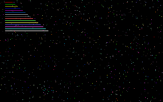
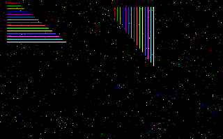
program test1; uses gfx256; var i : integer; BEGIN Graph320x200; for i:=0 to 999 do Pixel(random(320),random(200),random(256)); readln; for i:=1 to 15 do HorizLine(10,i*4,10+i*5,i); readln; for i:=1 to 15 do VertLine(160+i*4,10,10+i*5,i); readln; Text80x25; END. |
Downloads: [ Gfx256 unit | Test1 ]
The first loop (0 to 999) draws pixels randomly on the screen. This will look like a starfield.


